Rapid Vortex Fluidics Continuous Flow Synthesis of Amides and Local Anesthetic Lidocaine

Direct Amide Synthesis over Composite Magnetic Catalysts in a Continuous Flow Reactor
1
School of Engineering, University of Warwick, Coventry CV4 7AL, UK
2
Department of Chemical Engineering and Chemistry, Eindhoven University of Technology, 5600MB Eindhoven, The Netherlands
*
Author to whom correspondence should be addressed.
Received: 31 December 2020 / Revised: 13 January 2021 / Accepted: 16 January 2021 / Published: 20 January 2021
Abstract
Composite magnetic catalysts containing different amounts of sulfated titania (33–50 wt %) have been prepared by means of high energy ball-milling between TiO2 and NiFe2O4. The catalysts have been characterized with N2 adsorption/desorption isotherms, XRD, temperature programmed oxidation (TPO) and vibrating sample magnetometer (VSM). The catalytic activity was measured in the reaction of aniline and 4-phenylbutyric acid in the continuous mode under conventional and inductive heating. The effect of catalyst loading in the reactor on reaction and deactivation has been studied, indicating the catalyst containing 50 wt % titania gave the highest reaction rate and least deactivation. The operation in a flow reactor under inductive heating increased the amide yield by 25% as compared to conventional heating. The initial reaction rate decreased by 30% after a period of 15 h on stream. The catalyst activity was fully restored after a treatment with an air flow at 400 °C.
1. Introduction
Amide synthesis is considered as one of the most important reactions in the pharmaceutical industry. At the moment, the reaction is mainly performed utilizing a coupling agent [1], resulting in low atom-economy [2]. Direct amide synthesis over heterogeneous catalysts, using an acid and an amine provides a green and atom efficient way to form the amide bond. In addition, the catalyst can be easily recycled. Many heterogeneous catalysts have been studied to catalyze the direct amide reaction, such as sulfated tungstate [3], CeO2 [4], SiO2 [5] and Co based catalysts [6]. Sulfated TiO2 demonstrated a very high reaction rates and the yield of amides up to 90% at 115 °C in 12 h [7]. A nanostructured sulfated titania catalyst with uniform size was synthesized by the hydrothermal sol–gel method [8]. The amide yields over 75% were reported at a temperature of 110 °C. In our previous work [9], composite magnetic catalyst containing sulfated TiO2 also showed a better catalytic performance in the direct amidation of 4-phenylbutyric acid and aniline than those containing pure TiO2.
The reaction is carried out in a batch mode [6,7,10,11]. A continuous process has an advantage of easy scale up compared to a batch process. Comerford et al. [12] developed a continuous reactor packed with mesoporous structured silicas (SBA-15) or activated chromatographic K60 silica catalyst to synthesize N-(phenyl)-phenylacetamide at 150 °C. They used 12 mmol of each reagent (carboxylic acid and aniline) dissolved in toluene at an initial concentration of 0.6 M. The production rate was 0.349 g h−1 under optimized reaction conditions. However, in the case of K60 silica, the loading of the catalyst required was very high to obtain a noticeable amount of product. Britton et al. [13] developed a vortex fluidic device (VFD) for amide synthesis at 60 °C. The reaction between cyclohexylamine and butyrylchloride performed in the VFD provided the target amide in 94% yield in 80 s while the same reaction in the batch mode resulted in 9% yield for the same reaction time. The VFD operated at 6950 rpm enhancing the mixing of reactants on the microscale. While the method significantly improved the yield of several amides compared to those conducted in a batch reactor, acid chlorides were used instead of carboxylic acids to prevent possible reactor clogging upon salt formation.
In the last decades, mechanochemically assisted synthesis has become a reliable tool for preparation of different inorganic materials [14]. Some advantages of this method are the relative simplicity of the process, the absence of organic solvents and the possibility of obtaining new (metastable) phases with different properties to those of the conventionally prepared materials. Due to their magnetic properties, ferrite-based materials have drawn interest for different applications, including gas sensors and catalysts [15,16] and microwave absorbers [17,18]. Amongst all the spinel ferrites, NiFe2O4 has an inverse spinel structure and it is a well-known soft magnetic material, with relatively high values of saturation magnetization and low coercivity.
In this work, we apply solid state synthetic route to a mixture of NiFe2O4 and sulfated titania in order to develop a facile and clean preparation route for composite magnetic catalysts, and to investigate the possible differences in crystal structures and magnetic orderings from a TiO2/NiFe2O4 mechanical mixture [9]. The materials obtained are tested in the reaction between aniline and 4-phenylbutyric acid in a continuous flow reactor under conventional and inductive heating. Benchmarking experiments were also performed in a batch reactor.
2. Results and Discussion
2.1. Catalyst Characterization
Sulfated P25 has a surface area of 49.1 m2 g−1 while that of nickel ferrite was as low as 2.2 m2 g−1. The surface area of composite magnetic catalysts (CMCs) increased from 22.6 to 30.2 m2 g−1 and was by 5–6 m2 g−1 larger than the surface area of the mechanical mixture with the same chemical composition (Table 1). This means that the particle size decreases in the course of solid-state synthesis as smaller particles have a larger surface area.
The XRD patterns of composite catalysts, sulfated P25 and nickel ferrite are shown in Figure 1. The intensity of the titania peaks increased and at the same time the intensity of NiFe2O4 peaks decreased as the titania content in the samples increased. The major diffraction peaks at 25.38, 48.02 and 64.89° 2θ are attributed to the (101), (200) and (211) planes of the anatase phase respectively (JCPDS card no. 78-2486) and the peak located at 32.11° 2θ responds to the (110) plane of rutile. The peaks located at 30.67, 36.02, 37.63, 43.82, 54.82, 58.14 and 64.41° 2θ are assigned to the (220), (311), (222), (400), (422), (511) and (440) crystal planes of NiFe2O4 (JCPDS card no. 74-2081). The peaks at 31.43 and 41.35° 2θ are assigned to the (220) and (113) planes of α-Fe2O3 respectively (JCPDS card 33-0664). A small amount of α-Fe2O3 was formed during the synthesis of NiFe2O4 nanoparticles. Indexing of XRD patterns of all compositions revealed that there was no formation of new crystal phases during the mechanochemical synthesis of composite magnetic catalysts.
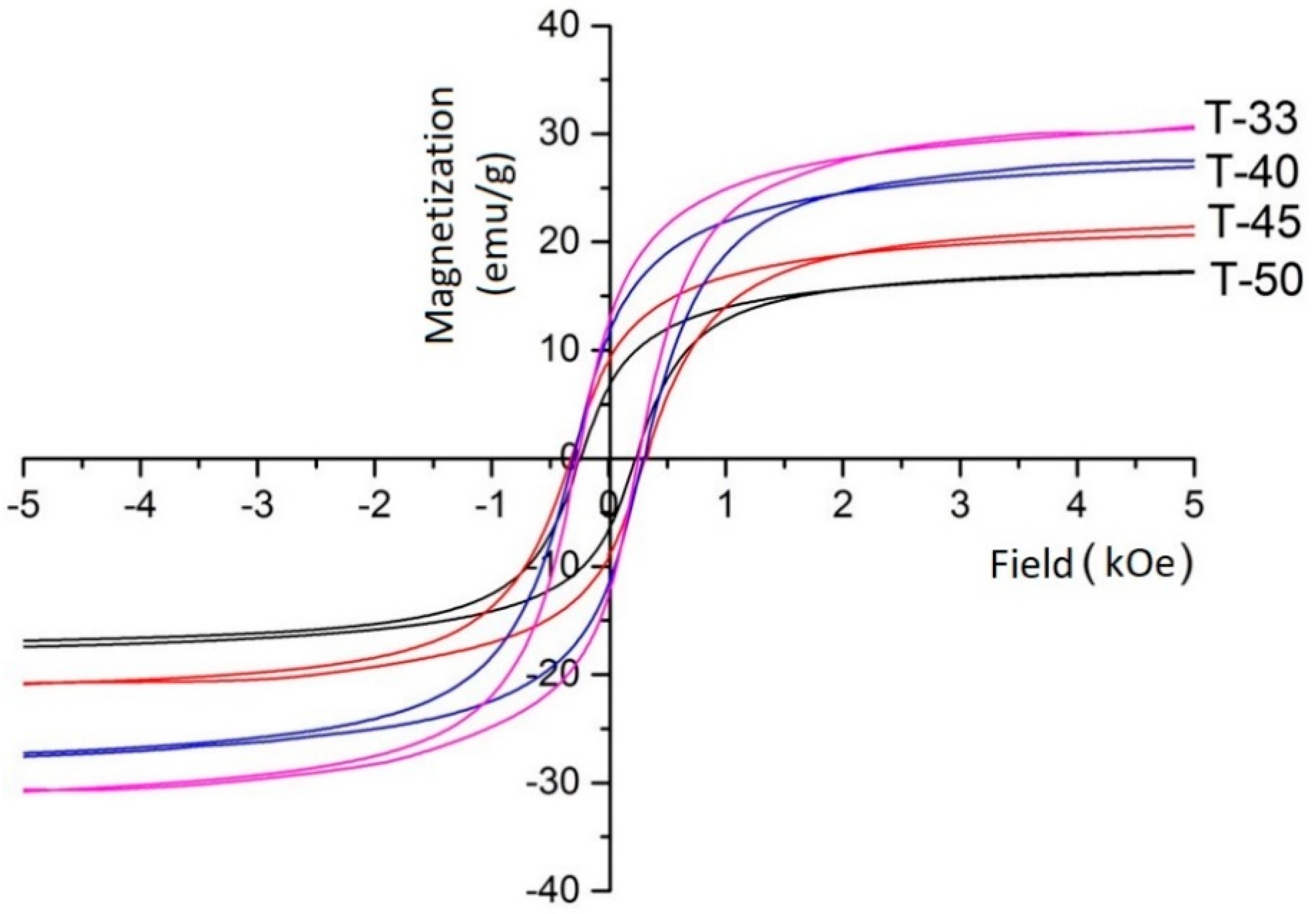
Figure 2 shows the magnetization curves of the CMCs. The saturation magnetization decreased gradually from 32.0 to 17.9 emu g−1 with the increase of the titania content in the samples. This can be explained by the dilution of the magnetic phase with non-magnetic titania particles. The coercivity first increased and then decreased with the increase of the titania content (Table 1). To understand this behavior, it should be mentioned that all samples were ferromagnetic with a magnetic domain size larger than the critical domain size for nickel ferrite (35 nm). A decrease grain size from 50 to 40 nm with increasing titania loading in the T-40 and T-45 samples was observed from the broadening of the XRD lines. The change in the average crystallite size influenced the coercivity of the CMC samples. The coercivity decreased with decreasing grain size until it would reach a maximum value at the critical size. However, this would require much longer ball milling time. On the contrary, the coercivity of T-50 was lower than that of all other samples. It was also caused by the addition of large amounts of titania, which reduced the mechanical impact between the ferrite particles and preserved the original grain size of nickel ferrite [9].
The heat generated in the radiofrequency (RF) field is directly proportional to the area of the hysteresis loop [19]. The hysteresis area decreased monotonously with the nickel ferrite content in the samples (Table 1). These data were in line with the specific absorption rate (SAR) data, which characterize the specific heating power (per gram) of the sample being placed under RF field.
As the titania content in the composite magnetic catalysts increased from 33 to 50 wt %, the SAR dropped from 1.7 to 1.0 W g−1. The CMC samples prepared demonstrated SARs that were more than twice below than those from a mechanical mixture of sulfated P25 and Ni ferrite (Table 1).
2.2. Catalytic Activity
The amide synthesis reaction between 4-phenylbutyric acid and aniline (Scheme 1) follows a second order kinetics [20] with an activation energy of 66 kJ mol−1 (Figure 3).
The rate constants increased from 0.21 mL·mol−1 s−1 at 130 °C to 1.26 mL·mol−1 s−1 at 170 °C. The reaction rates are listed in Table 2. The rate in the batch reactor at 150 °C was rather close to that (0.041 µmol g−1 s−1) reported by Comerford et al. [12] who studied a reaction between phenylacetic acid and aniline over a K60 silica catalyst.
Efficient mass and heat transfer was achieved in the batch reactor. The Arrhenius plot obtained showed a straight line demonstrating the absence of diffusional limitations. However, the catalyst average temperature in the C-Flow reactor was by 6 K lower than that in the batch reactor. This value was estimated from the data obtained in both reactors and the activation energy of the reaction of 66 kJ mol−1. This observation allows one to conclude over a radial temperature gradient in the C-Flow reactor due to relatively slow heat transfer from the outer wall to the center of the catalyst bed.
It should also be mentioned that the catalyst deactivation occurred at all conditions while it became much faster at 170 °C. To maintain the catalytic performance, the catalyst regeneration was carried out by heating the catalyst bed in air flow, as it will be discussed in the next section. Balancing the reaction and deactivation rates, a temperature of 150 °C was chosen for further experiments in the RF-flow reactor.
The reaction rate in the RF-heated reactor approached that in the batch reactor (Table 2). For a proper comparison between different catalysts, the same amount of titania was loaded in the RF-flow reactor by increasing the total weight of CMC. This allowed us to maintain the same residence time in the reactor. Due to volumetric heating in the RF-Flow reactor, the radial temperature gradient was eliminated, leading to a higher reaction rate at the same temperature on the outer reactor wall. Table 3 compares the initial reaction rate over all four CMCs in the RF-flow reactor.
2.3. Catalyst Deactivation
The deactivation rate at 150 °C was considerably reduced in the RF-flow reactor over all CMCs studied (Figure 4). It should be mentioned that T-33 had a higher Ni ferrite loading and therefore less electrical current was needed to maintain the same temperature. Therefore it could be assumed that the volumetric power generation rate inside a single pellet was lower in the T-33 sample as compared to T-50. This, in turn, reduced the magnitude of intrapellet temperature gradient in T-33 and resulted in a longer period of constant activity. Indeed, the reaction rate over T-33 remained rather constant for 300 min as compared to 100 min for T-50. Nevertheless, once the deactivation started, it proceeded much faster in the catalyst with the highest NiFe2O4 loading.
It can be seen from Table 3 that the initial reaction rate increased by 35% with increasing the titania content in the catalysts from 33 to 50 wt %. Additionally, the specific reaction rate (the rate normalized per surface area of titania) increased to the maximum value in the T-50 sample (Table 3). A possible reason can be related to physical blockage of active sides by ferrite nanoparticles in the samples with high ferrite content. Compared to the fresh catalysts, surface area of each catalyst dropped by 16–20% after the reaction (Table 3).
There exist several possible mechanisms of the catalyst deactivation. One of them is related to the blockage of active sites with water molecules produced in the reaction. Another mechanism causing the deactivation is related to the deposition of carbon-containing species produced by decomposition reactants involved at relatively high reaction temperature. The carbon-containing deposit formed in the pores can block them for diffusion of reactants, resulting in the decrease of the catalytic surface area available for the reaction. The surface area can also be reduced by the sintering of the catalysts caused by the high temperature. Finally the loss of sulfate groups in the course of reaction can also be responsible for deactivation.
The specific production rates over all fresh CMCs were approximately the same (about 3.5–3.9 nmol·m−2·s−1, Table 3) and the values over the spent catalysts were nearly the same too. This allowed us to conclude that the loss of active sites could be excluded. The amount of carbon deposits formed in each catalyst was analyzed by temperature programmed oxidation (TPO). With the catalyst temperature monotonously increasing from 20 to 600 °C, the CO2 profiles were recorded over spent catalysts (Figure 5). It can be seen that at least two types of carbon species were observed. One of them was oxidized near 290 °C and the main CO2 peak was centered at around 370 °C. The total amount of carbon species formed was slightly higher in the samples with lower titania content, which was consistent with the degree of catalyst deactivation (Table 3). Both the specific surface area and the reaction rate dropped by 18–20% over 600 min on stream in the flow reactor. This indicated that the deposition of organic species onto the active sites was the main reason for the deactivation.
Based on the TPO data, the catalyst regeneration was done after 15 h on stream by calcination in an air flow at 400 °C for 1 h. The reaction rate over the fresh T-50 and over the samples regenerated one and two times (called T-50-1 and T-50-2 hereafter) is shown in Figure 6. It can be seen that the initial reaction rate decreased by approximately 30% after the first run and by half in the second and third runs.
The TGA analysis (not shown here) demonstrated that all coke was burnt out at the end of regeneration cycle. The surface areas of T-50-1 decreased slightly from 30.2 to 29.1 m2 g−1 after the first regeneration at 400 °C and that of T2-50-2 deceased further to 28.3 m2 g−1 after the second regeneration.
3. Experimental
3.1. Synthesis of Composite Magnetic Catalysts
The composite magnetic catalysts (CMCs) were prepared by ball milling of a mixture of nickel ferrite and sulfated titania powders in an agate jar (Retsch planetary ball mill PM 400) with six balls at 300 rpm for 30 min. Before the synthesis, the sulfated titania and nickel ferrite could be distinguished by their white and brown colors, while they became uniform dark brown powders after the synthesis. The nanostructured nickel ferrite powder was synthesized by the method described elsewhere [21]. The sulfated titania particles were obtained by sulfation of commercial P25 titania (Sigma Aldrich, St. Louis, MO, USA) with a 0.2 M sulfuric acid solution at 20 °C for 3 h to obtain a 7.5 wt % sulfur loading. The solution was dried and then calcined at 400 °C for 2 h. After the sulfation treatment, the total number of the Lewis acid sites remained virtually the same, however their strength was considerably increased [22]. There is an optimum value at a 7.5 wt % sulfur loading. The composite magnetic catalysts will be labeled as T-X hereafter, where X stands for the titania weight fraction.
3.2. Catalyst Characterization
The specific surface area and the total pore volume were determined by N2 adsorption/desorption isotherms using an ASAP 2020 apparatus (Micromeritics). Prior to the measurements, the samples were degassed under N2 at 250 °C for 1 h. The phase composition was determined with powder X-ray diffraction (XRD) using a diffractometer (PANalytical Empyrean, Almelo, The Netherlands) with Cu Kα radiation at 45 kV. The spectra were recorded at a scanning rate of 1° 2θ min−1. The thermogravimetric analysis was performed with a STA 449 C Netzsch Analyzer at a 10 mL min−1 flow of 20 vol.% O2 mixture (balance is N2) at a heating rate of 10 K min−1 from room temperature to 800 °C.
Magnetization (M) as a function of the magnetic field (H) was measured by a vibrating sample magnetometer (VSM Oxford MagLab). The saturation magnetization (Ms) and coercivity (HC) were evaluated from the hysteresis loop registered at 20 °C. The specific adsorption rate (SAR) under the RF field at 300 kHz was measured following the procedure described in [9].
3.3. Catalytic Activity Measurements
A schematic view of the experimental set-up is shown in Figure 7a. A solution of 0.1 M aniline in p-xylene and a 0.1 M solution of 4-phenylbutyric acid in p-xylene was fed with two HPLC pumps (Shimadzu LC-20ADXR, Kyoto, Japan). A backpressure controller was placed after the reactor to maintain a pressure of 7 bar inside the reactor, which was necessary to avoid solvent boiling. The liquid samples were analyzed off-line with a gas chromatograph (Shimadzu GC-2010) equipped a CP-sil 5CB capillary column (length 30 m, internal diameter 250 µm) and with an FID detector. Decane was used as an internal standard. The catalyst was heated by an 8-turn induction coil with a length of 70 mm connected to a 1.2 kW RF generator (Ambrell Easyheat model 0112, Rochester, NY, USA). The coil and electronic module were cooled with water circulating at 20 °C. The water temperature in the coil was controlled with a chiller (WKL1000 Lauda, not shown in the schematic view). To avoid temperature nonuniformity in the reactor, the conductive thermal resistance in the solid bed should be much smaller, compared to the combined thermal resistance of the reactor wall, insulation, and natural convection [23]. In this study, to confirm the absence of temperature gradient along the reactor length, a thermal camera (FLIR A655-25) was used. The temperature was controlled at the catalyst position with a fiber optic sensor (sensitive zone: 5 mm Opsens, OTG) attached to the outer reactor wall. A feedback controller was made with LabVIEW software regulating the electrical current (and therefore the magnetic field) in the induction coil. The outer surface of the reactor was insulated with glass wool. A few openings were made in the insulation layer for the temperature readings with the thermal camera.
The catalyst (pellet size: 125–250 µm) was loaded in a tubular reactor with an internal diameter of 6.6 mm (Figure 7b). A layer of glass beads (fraction: 106–125 µm) was placed from both sides from the catalyst bed. The length of the catalyst bed was changed in the range 10–14 mm depending on the titania loading in the composite catalysts. The preheating of the reaction mixture was realized in a 5 mm section filled with Fe3O4 particles (fraction: 125–250 µm).
Spent catalysts (after the reaction) were separated from the glass beads by a magnet and then washed by p-xylene. After drying at 110 °C overnight, the catalysts were calcined at the desired temperature under air flow. The catalysts after the regeneration step will be labeled as TR-X-Y, where Y represents the number of the regeneration cycles.
The benchmarking catalytic tests were carried out in a 250 mL continuously stirred tank reactor (Parr). Prior to the experiments, the reactor was purged by nitrogen. Then, a mixture of 0.05 M aniline and 4-phenylbutyric acid (PBA) in p-xylene and the catalyst (165 mg, pellet size: 125–250 µm) was loaded. The reactor was pressurized to 6 bars and heated to a desired temperature. Samples of the reaction mixture were collected from the reactor at regular intervals.
Temperature programmed oxidation profiles of spent catalysts were recorded with a mass spectrometer (OMNI star). The catalyst (50 mg) was placed in a tubular reactor. A mixture of 20 vol.% O2 flow (balance-N2) was fed and the temperature was raised linearly from 20 °C to the desired temperature at a rate of 5 K min−1.
4. Conclusions
The mechanochemical synthesis method proved to be an efficient, clean, scalable and low-cost route to prepare titania based composite magnetic catalysts for direct amide synthesis. A mixture of 50 wt % TiO2 and 50 wt % Ni ferrite demonstrated the best performance in the reaction between 4-pheylbutyric acid and aniline in a flow reactor under inductive heating. The reaction rate under inductive heating increased by 25% in the continuous mode operation as compared with conventional heating at the same temperature. The reaction rate decreased by 30% after a period of 15 h on stream. The deposition of carbon-containing species onto the active sites was the main reason for the deactivation. The catalyst activity was fully restored after a treatment with an air flow at 400 °C.
Author Contributions
Y.L. performed experimental work, interpretation of results and she prepared an initial draft of the paper. E.V.R. was responsible for the paper consistency and final corrections. Both authors have read and agreed to the published version of the manuscript.
Funding
This research was funded by the European Research Council (ERC) project 279867.
Institutional Review Board Statement
Not applicable.
Informed Consent Statement
Not applicable.
Data Availability Statement
All data needed to support the conclusions in the paper are present in the paper. Additional data related to this paper may be requested from the authors.
Acknowledgments
Financial support provided by the European Research Council (ERC) project 279867 is gratefully acknowledged. Y. Liu would like to thank Nikolay Cherkasov from the University of Warwick for his help with the TPO experiments.
Conflicts of Interest
The authors declare no conflict of interest.
References
- Valeur, E.; Bradley, M. Amide bond formation: Beyond the myth of coupling reagents. Chem. Soc. Rev. 2009, 38, 606–631. [Google Scholar] [CrossRef]
- Constable, D.J.C.; Dunn, P.J.; Hayler, J.D.; Humphrey, G.R.; Leazer, J.J.L.; Linderman, R.J.; Lorenz, K.; Manley, J.; Pearlman, B.A.; Wells, A.; et al. Key green chemistry research areas—A perspective from pharmaceutical manufacturers. Green Chem. 2007, 9, 411–442. [Google Scholar] [CrossRef]
- Chaudhari, P.S.; Salim, S.D.; Sawant, R.V.; Akamanchi, K.G. Sulfated tungstate: A new solid heterogeneous catalyst for amide synthesis. Green Chem. 2010, 12, 1707–1710. [Google Scholar] [CrossRef]
- Siddiki, S.H.; Touchy, A.S.; Tamura, M.; Shimizu, K.-I. Versatile and sustainable alcoholysis of amides by a reusable CeO2 catalyst. RSC Adv. 2014, 4, 35803–35807. [Google Scholar] [CrossRef]
- Comerford, J.W.; Clark, J.H.; MacQuarrie, D.J.; Breeden, S.W. Clean, reusable and low cost heterogeneous catalyst for amide synthesis. Chem. Commun. 2009, 18, 2562–2564. [Google Scholar] [CrossRef]
- Bai, C.; Yao, X.; Li, Y. Easy access to amides through aldehydic C–H bond functionalization catalyzed by heterogeneous Co-based catalysts. ACS Catal. 2015, 5, 884–891. [Google Scholar] [CrossRef]
- Hosseini-Sarvari, M.; Sodagar, E.; Doroodmand, M.M. Nano sulfated titania as solid acid catalyst in direct synthesis of fatty acid amides. J. Org. Chem. 2011, 76, 2853–2859. [Google Scholar] [CrossRef] [PubMed]
- Nagarajan, S.; Ran, P.; Shanmugavelan, P.; Sathishkumar, M.; Ponnuswamy, A.; Nahm, K.S.; Kumar, G.G. The catalytic activity of titania nanostructures in the synthesis of amides under solvent-free conditions. New J. Chem. 2012, 36, 1312–1319. [Google Scholar] [CrossRef]
- Houlding, T.K.; Gao, P.; Degirmenci, V.; Tchabanenko, K.; Rebrov, E.V. Mechanochemical synthesis of TiO2/NiFe2O4 magnetic catalysts for operation under RF field. Mater. Sci. Eng. B 2015, 193, 175–180. [Google Scholar] [CrossRef]
- Lundberg, H.; Tinnis, F.; Adolfsson, H. Direct amide coupling of non-activated carboxylic acids and amines catalysed by zirconium(IV) chloride. Chem. Eur. J. 2012, 18, 3822–3826. [Google Scholar] [CrossRef]
- Perreux, L.; Loupy, A.; Volatron, F. Solvent-free preparation of amides from acids and primary amines under microwave irradiation. Tetrahedron 2002, 58, 2155–2162. [Google Scholar] [CrossRef]
- Comerford, J.W.; Farmer, T.J.; MacQuarrie, D.J.; Breeden, S.W.; Clark, J.H. Mesoporous structured silica—An improved catalyst for direct amide synthesis and its application to continuous flow processing. ARKIVOC 2012, 7, 282–293. [Google Scholar] [CrossRef][Green Version]
- Britton, J.; Chalker, J.M.; Raston, C.L. Rapid Vortex Fluidics: Continuous flow synthesis of amides and local anesthetic lidocaine. Chem. Eur. J. 2015, 21, 10660–10665. [Google Scholar] [CrossRef] [PubMed]
- James, S.L.; Adams, C.J.; Bolm, C.; Braga, D.; Collier, P.; Friščić, T.; Grepioni, F.; Harris, K.D.M.; Hyett, G.; Jones, W.; et al. Mechanochemistry: Opportunities for new and cleaner synthesis. Chem. Soc. Rev. 2011, 41, 413–447. [Google Scholar] [CrossRef] [PubMed][Green Version]
- Ranganath, K.V.S.; Shaikh, M.; Sahu, A.; Sarvani, G. Catalytic activity of functionalized spinels. Curr. Org. Chem. 2017, 21, 2573–2584. [Google Scholar] [CrossRef]
- Šutka, A.; Gross, K.A. Spinel ferrite oxide semiconductor gas sensors. Sens Actuators B Chem. 2016, 222, 95–105. [Google Scholar] [CrossRef]
- Ahmad, R.; Gul, I.H.; Zarrar, M.; Anwar, H.; Niazi, M.B.K.; Khan, A. Improved electrical properties of cadmium substituted cobalt ferrites nano-particles for microwave application. J. Magn. Magn. Mater. 2016, 405, 28–35. [Google Scholar] [CrossRef]
- Gao, P.; Rebrov, E.V.; Verhoeven, T.M.W.G.M.; Schouten, J.C.; Kleismit, R.; Kozlowski, G.; Cetnar, J.; Turgut, Z.; Subramanyam, G. Structural investigations and magnetic properties of sol-gel Ni0.5Zn0.5Fe2O4 thin films for microwave heating. J. Appl. Phys. 2010, 107, 044317. [Google Scholar] [CrossRef][Green Version]
- Houlding, T.K.; Rebrov, E.V. Application of alternative energy forms in catalytic reactor engineering. Green Process. Synth. 2012, 1, 19–31. [Google Scholar] [CrossRef]
- Charville, H.; Jackson, D.A.; Hodges, G.; Whiting, A.; Wilson, M.R. The Uncatalyzed direct amide formation reaction—Mechanism studies and the key role of carboxylic acid H-bonding. Eur. J. Org. Chem. 2011, 30, 5981–5990. [Google Scholar] [CrossRef]
- Gao, P.; Hua, X.; Degirmenci, V.; Rooney, D.; Khraisheh, M.; Pollard, R.; Bowman, R.M.; Rebrov, E.V. Structural and magnetic properties of Ni1−xZnxFe2O4 (x = 0, 0.5 and 1) nanopowders prepared by sol–gel method. J. Magn. Magn. Mater. 2013, 348, 44–50. [Google Scholar] [CrossRef]
- Liu, Y.; Cherkasov, N.; Gao, P.; Fernández, J.; Lees, M.R.; Rebrov, E.V. The enhancement of direct amide synthesis reaction rate over TiO2 @SiO2 @NiFe2O4 magnetic catalysts in the continuous flow under radiofrequency heating. J. Catal. 2017, 355, 120–130. [Google Scholar] [CrossRef][Green Version]
- Chatterjee, S.; Houlding, T.K.; Doluda, V.Y.; Molchanov, V.P.; Matveeva, V.G.; Rebrov, E.V. Thermal behavior of a catalytic packed-bed milli-reactor Operated under Radio Frequency Heating. Ind. Eng. Chem. Res. 2017, 56, 13273–13280. [Google Scholar] [CrossRef][Green Version]
Figure 1. XRD patterns of composite catalysts, nickel ferrite and sulfated P25.
Figure 1. XRD patterns of composite catalysts, nickel ferrite and sulfated P25.
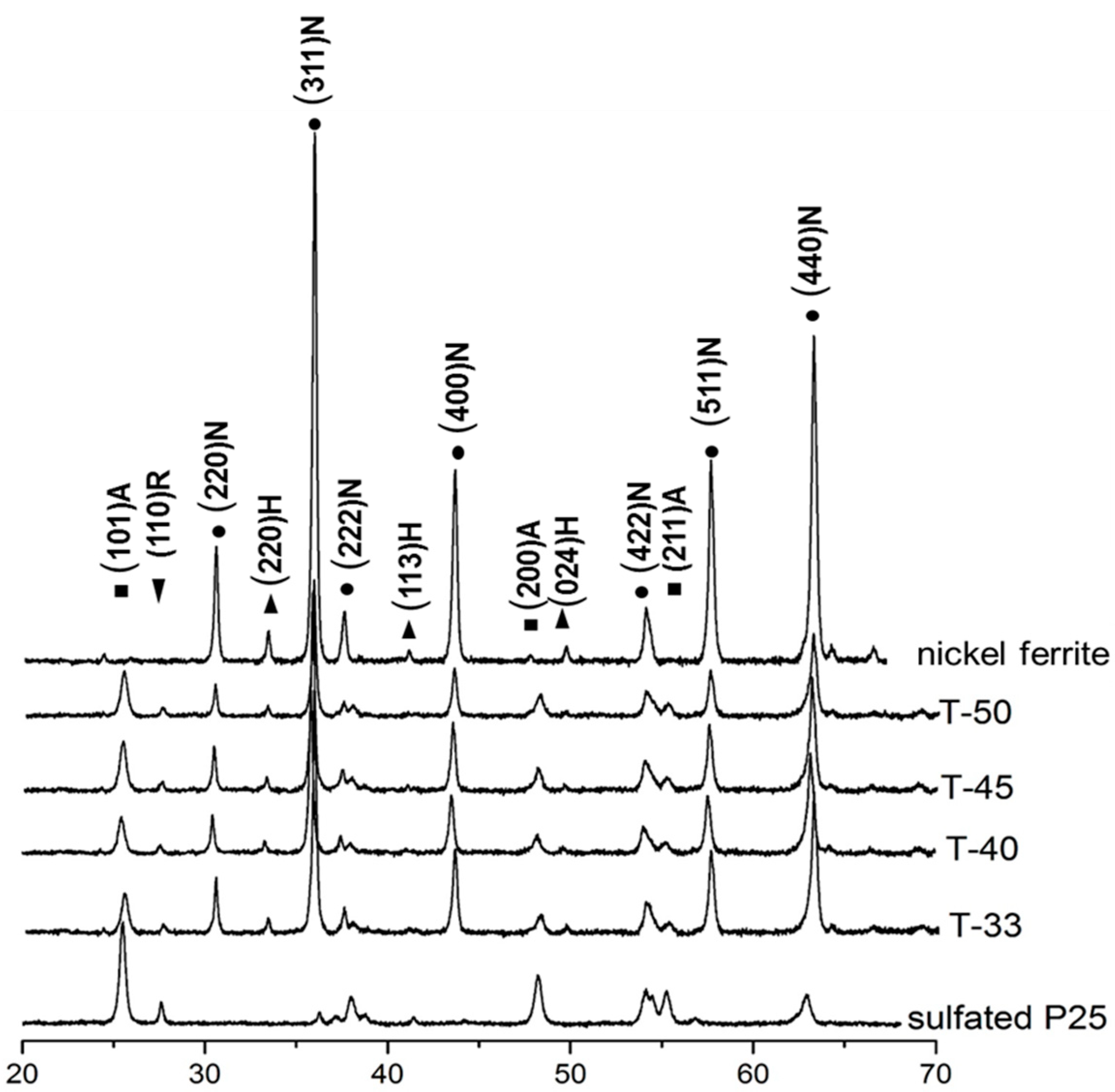
Figure 2. Magnetization curves of composite catalysts measured at 20 °C.
Figure 2. Magnetization curves of composite catalysts measured at 20 °C.
Scheme 1. The scheme of the 4,N-diphenylbutynamide synthesis.
Scheme 1. The scheme of the 4,N-diphenylbutynamide synthesis.

Figure 3. The amide yield as a function of time over T-50 in the batch reactor with a mixture of aniline (0.05 M) and 4-phenylbutyric acid (0.05 M) in p-xylene. The catalyst weight: 165 mg. Pressure: 6 bar.
Figure 3. The amide yield as a function of time over T-50 in the batch reactor with a mixture of aniline (0.05 M) and 4-phenylbutyric acid (0.05 M) in p-xylene. The catalyst weight: 165 mg. Pressure: 6 bar.
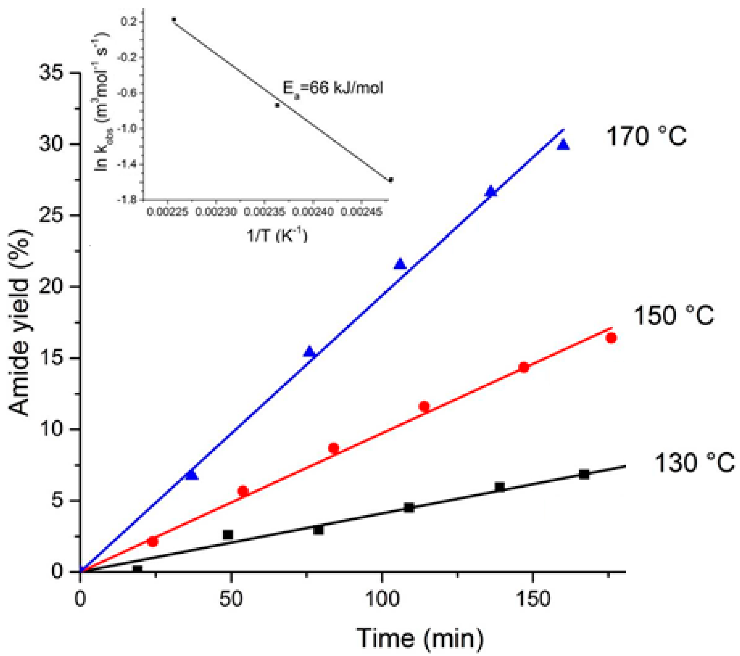
Figure 4. Reaction rate over composite magnetic catalysts in the RF-flow reactor as a function of time on stream. Reaction conditions: concentration of 4-phenylbutyric acid: 50 mmol L−1, concentration of aniline: 50 mmol L−1. Flow rate: 110 µL min−1. Temperature: 150 °C, pressure: 7 bar.
Figure 4. Reaction rate over composite magnetic catalysts in the RF-flow reactor as a function of time on stream. Reaction conditions: concentration of 4-phenylbutyric acid: 50 mmol L−1, concentration of aniline: 50 mmol L−1. Flow rate: 110 µL min−1. Temperature: 150 °C, pressure: 7 bar.
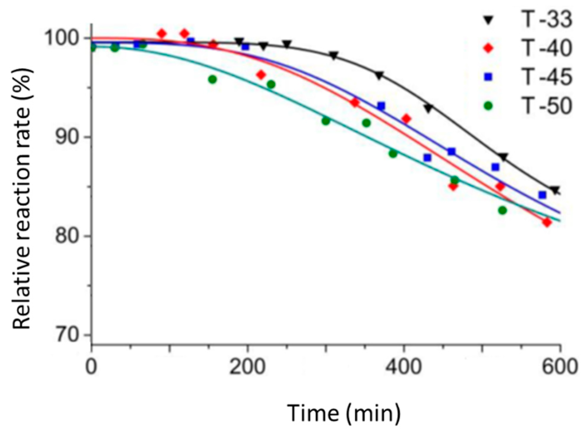
Figure 5. Temperature programmed oxidation of spent catalysts with a mixture of 20 vol.% O2 in He. Heating rate: 5 K min−1.
Figure 5. Temperature programmed oxidation of spent catalysts with a mixture of 20 vol.% O2 in He. Heating rate: 5 K min−1.

Figure 6. Reaction rate as a function of time over the fresh (T-50) and regenerated (T-50-1 and T-50-2) catalysts. Catalyst weight: 526 mg, Reaction conditions: concentration of 4-phenylbutyric acid: 50 mmol L−1, concentration of aniline: 50 mmol L−1. Flow rate: 110 µL min−1. Temperature: 150 °C, pressure: 7 bar.
Figure 6. Reaction rate as a function of time over the fresh (T-50) and regenerated (T-50-1 and T-50-2) catalysts. Catalyst weight: 526 mg, Reaction conditions: concentration of 4-phenylbutyric acid: 50 mmol L−1, concentration of aniline: 50 mmol L−1. Flow rate: 110 µL min−1. Temperature: 150 °C, pressure: 7 bar.
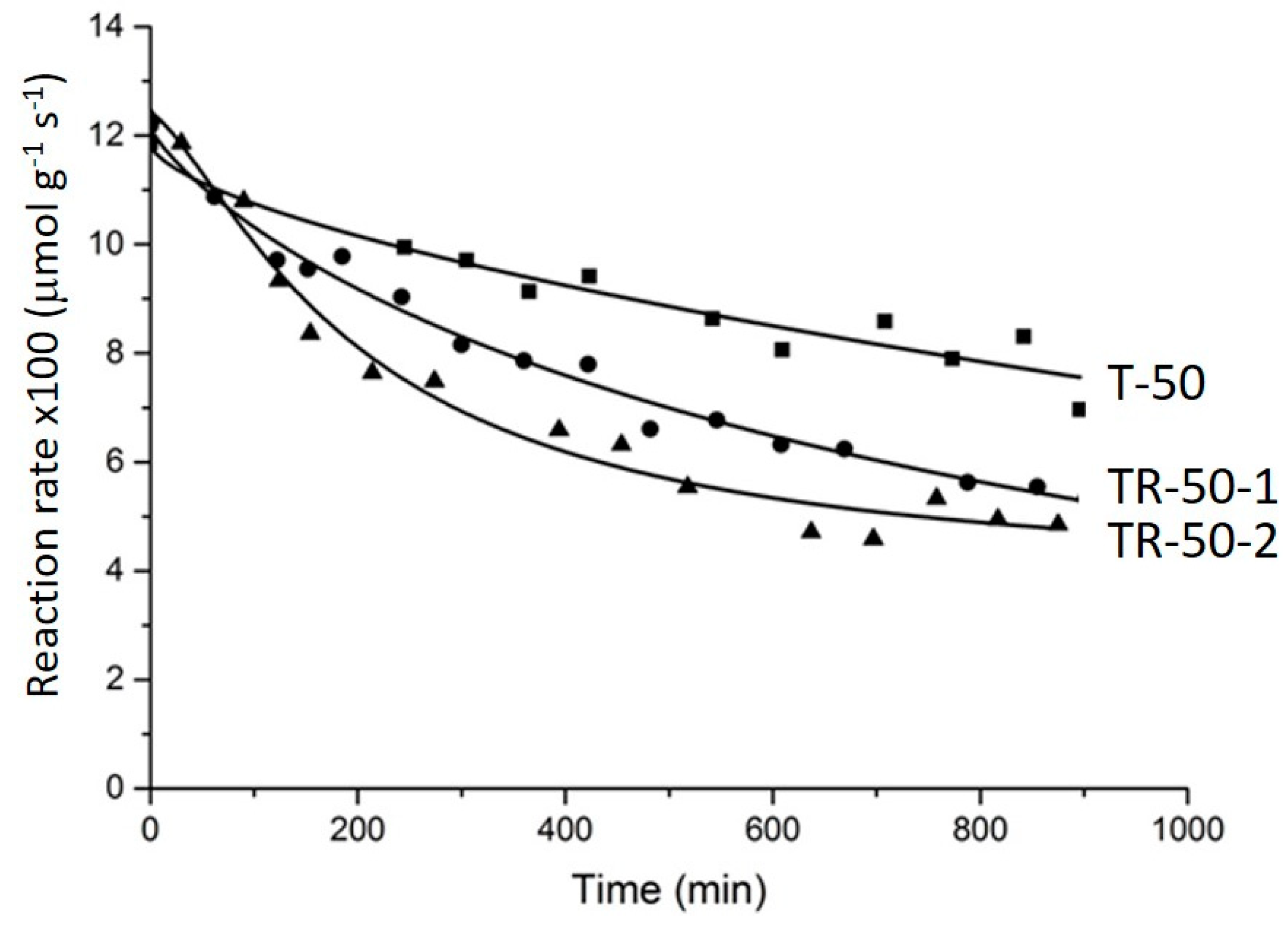
Figure 7. (a) A schematic view of the experimental set-up. A characteristic temperature field measured with the IR-camera shown in the top right corner. Blue color corresponds to 20 °C and white color: 130 °C. (b) A schematic view of the packed bed.
Figure 7. (a) A schematic view of the experimental set-up. A characteristic temperature field measured with the IR-camera shown in the top right corner. Blue color corresponds to 20 °C and white color: 130 °C. (b) A schematic view of the packed bed.
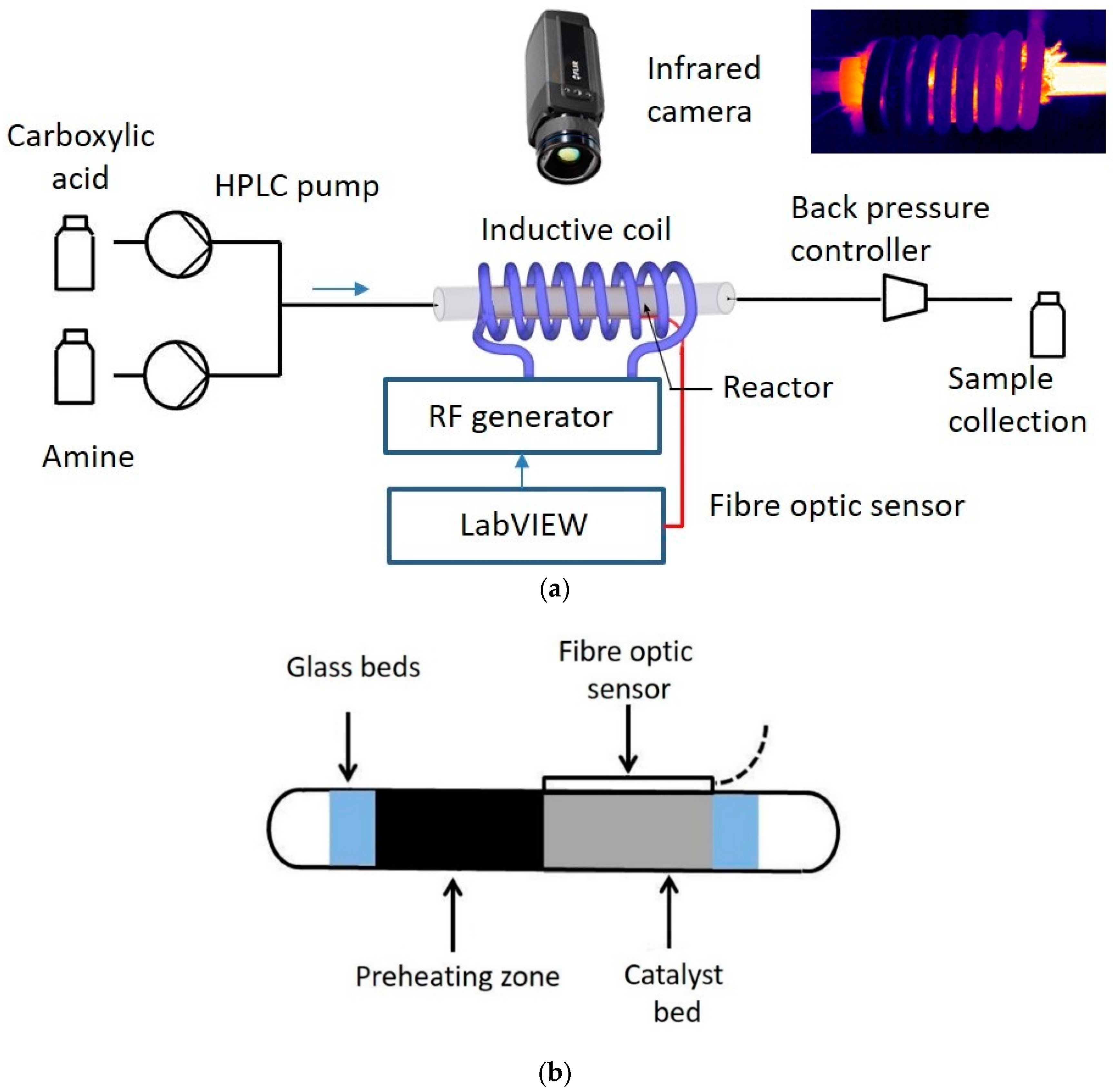
Table 1. Specific surface area and specific absorption rate of composite magnetic catalysts.
Table 1. Specific surface area and specific absorption rate of composite magnetic catalysts.
| Sample | Surface Area (m2 g−1) | SAR (W g−1) | MS (emu g−1) | HC (Oe) | Hysteresis Area (kJ m−3) | ||
|---|---|---|---|---|---|---|---|
| CMC | MM | CMC | MM | ||||
| Ni ferrite | - | 2.2 | - | 4.7 | 71.5 | 150 | 1.752 |
| Sulfated P25 | - | 49.1 | - | 0 | 0 | 0 | 0 |
| T-33 | 22.6 | 17.8 | 1.7 | 3.1 | 32.0 | 260 | 1.157 |
| T-40 | 27.6 | 21.0 | 1.3 | 2.8 | 28.1 | 300 | 1.025 |
| T-45 | 29.3 | 23.3 | 1.2 | 2.5 | 21.6 | 310 | 0.786 |
| T-50 | 30.2 | 25.7 | 1.0 | 2.4 | 17.9 | 240 | 0.646 |
Table 2. Reaction rate in the batch reactor, conventionally heated flow reactor and RF-heated flow reactor over the T-50 catalyst.
Table 2. Reaction rate in the batch reactor, conventionally heated flow reactor and RF-heated flow reactor over the T-50 catalyst.
| Temperature (°C) | Reaction Rate (µmol gTiO2 −1 s−1) | ||
|---|---|---|---|
| Batch | C-Flow | RF-Flow | |
| 130 | 0.0194 | 0.0150 | - |
| 150 | 0.0250 | 0.0187 | 0.0236 |
| 170 | 0.0510 | 0.0221 | - |
Table 3. Reaction rate over CMCs in the RF-flow reactor.
Table 3. Reaction rate over CMCs in the RF-flow reactor.
| Sample Code | Catalyst Weight (mg) | Initial Reaction Rate (µmol·gCMC −1·s−1) | Specific Reaction Rate (nmol·m−2·s−1) | Surface Area of Spent CMC a (m2 g−1) | Coke Weight (mg gCMC −1) |
|---|---|---|---|---|---|
| T-33 | 782 | 0.076 | 3.4 | 18.4 (−19%) | 9.5 |
| T-40 | 653 | 0.096 | 3.5 | 22.5 (−18%) | 10.3 |
| T-45 | 595 | 0.0104 | 3.5 | 23.2 (−20%) | 8.8 |
| T-50 | 526 | 0.0118 | 3.9 | 25.4 (−16%) | 8.4 |
| Publisher's Note: MDPI stays neutral with regard to jurisdictional claims in published maps and institutional affiliations. |
© 2021 by the authors. Licensee MDPI, Basel, Switzerland. This article is an open access article distributed under the terms and conditions of the Creative Commons Attribution (CC BY) license (http://creativecommons.org/licenses/by/4.0/).
Source: https://www.mdpi.com/2073-4344/11/2/146/htm
0 Response to "Rapid Vortex Fluidics Continuous Flow Synthesis of Amides and Local Anesthetic Lidocaine"
Post a Comment